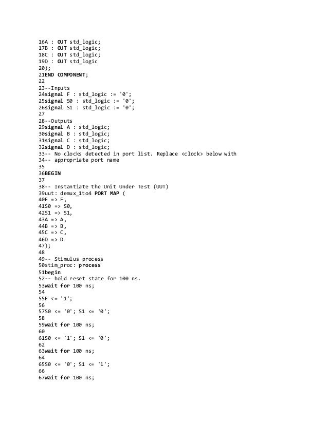
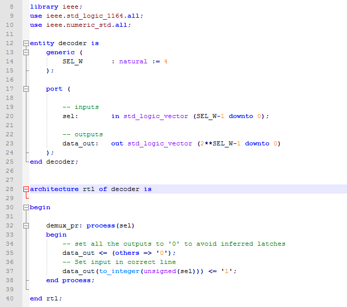
- Vhdl Code For Demultiplexer
- Vhdl Code For Demultiplexer Using Behavioural Modelling
- Vhdl Code For Multiplexer And Demultiplexer
- Inverse Multiplexer Vhdl
- Vhdl Code For Demultiplexer Using Structural Modelling
- Vhdl Code For 1 8 Demultiplexer
- VHDL code for 4 Bit adder; VHDL code for register; VHDL code for multiplexer; VHDL code for counter; VHDL code for addition of 4BITADDER with user library; VHDL code for Ring Counter; VHDL code for DATAPATH for summation of 8 down to. VHDL code for 4 Bit multiplier using NAND gate; VHDL code for general datapath; VHDL code for Adder.
- Demultiplexer with vhdl code 1. Title: 1:4 Demultiplexer using Xilinx Software: Xilinx ISE I. Introduction Demultiplexer (Demux) The action or operation of a demultiplexer is opposite to that of the multiplexer. As inverse to the MUX, demux is a one-to-many circuit.
1X8 DEMUX VHDL source code This page of VHDL source code covers 1X8 DEMUX vhdl code.
- VLSI Design Tutorial
- VHDL Programming

- Verilog
- VLSI Design Useful Resources
- Selected Reading
This chapter explains the VHDL programming for Combinational Circuits.
VHDL Code for a Half-Adder
Waveforms
VHDL Code for a Full Adder
Waveforms
VHDL Code for a Half-Subtractor
Waveforms
VHDL Code for a Full Subtractor
Waveforms
VHDL Code for a Multiplexer
Vhdl Code For Demultiplexer
Waveforms
VHDL Code for a Demultiplexer
Waveforms
VHDL Code for a 8 x 3 Encoder
Waveforms
VHDL Code for a 3 x 8 Decoder
Waveforms
Vhdl Code For Demultiplexer Using Behavioural Modelling
VHDL Code – 4 bit Parallel adder
Waveforms
VHDL Code – 4 bit Parity Checker
Waveforms
Vhdl Code For Multiplexer And Demultiplexer


VHDL Code – 4 bit Parity Generator
Waveforms
In previous tutorials VHDL tutorial (#6), we built a circuit for D Morgan’s Theorems in VHDL and verified its output to prove D Morgan’s theorems.
(If you are not following this VHDL tutorial series one by one, you are requested to go through all previous tutorials of these series before going ahead in this tutorial)
In this tutorial,

- We shall write a VHDL program to build all other gates (AND, OR, NOT, XOR, NOR, etc.) using only NAND gates
- Verify the output waveform of the program (digital circuit) with the truth table of AND, OR, NOT, XOR, NOR gates
Digital Circuit
Truth Table
Now we shall write a VHDL program, compile it, simulate it, and get the output in the form of a waveform. Finely, we shall verify those output waveforms with a given truth table.
(Please go through step by step procedure given in VHDL-tutorial 3 to create a project, edit and compile the program, create waveform file, simulate the program, and generate output waveforms.)
VHDL Program:
Inverse Multiplexer Vhdl
library IEEE;
use IEEE.STD_LOGIC_1164.ALL;
entity nand_uni_gate is
Port ( a,b : in std_logic;
y_not,y_and, y_or, y_xor: out std_logic
);
end nand_uni_gate;
architecture nand_uni_gate_arch of nand_uni_gate is
begin
y_not <= a nand a;
y_and <= (a nand b) nand (a nand b);
y_or <= (a nand a) nand (b nand b);
y_nor <=((a nand a) nand (b nand b)) nand ((a nand a) nand (b nand b));
y_xor <= (a nand (a nand b)) nand (b nand (a nand b));
end nand_uni_gate_arch;

“entity” describes input-output connections of a digital circuit. As per our circuit given above, we have only two inputs ‘A’ and ‘B’ and five outputs for five circuits of different gates build using the NAND gate only.
“architecture” describes the operation of the circuit – means how the output is generated from a given input.
(To know more and get more details about VHDL program(s), please go through the first two tutorials VHDL tutorial 1 and VHDL tutorial 2 of these series.)
Next, compile above program – create waveform file with all inputs and outputs listed – simulate the project and you will get the following result
Simulation Waveform
From these output waveforms, we can easily say that the output of different gate circuits built using only NAND gates is the same as the output of a particular gate.
Vhdl Code For Demultiplexer Using Structural Modelling
That means we can design all other gates using only the NAND gate, so the NAND gate is a universal gate.
Vhdl Code For 1 8 Demultiplexer
In the next tutorial, we shall prove the NOR gate as a universal gate by designing AND, OR, NOT, NAND, and XNOR gates using only NOR gate.
